Wednesday, June 25, 2014

Belt Drives

A belt is a looped strip of flexible material used to mechanically link two or more rotating shafts. A belt drive offers smooth transmission of power between shafts at considerable distance. Belt drives are used as source of motion to transfer to efficiently transmit power or to track relative movement.

Image source : wwag.com

Types of Belt Drives:

In a two pulley system, depending upon direction the belt drives the pulley, the belt drives are divided into two types. They are open belt drive and crossed belt drive. The two types of belt drives are discussed below in brief.

Open belt drives :

open belt drive
An open belt drive is used to rotate the driven pulley in the same direction of driving pulley.  In motion of belt drive, power transmission results makes one side of pulley more tightened compared to the other side.  In horizontal drives, tightened side is always kept in the lower side of two pulleys because the sag of the upper side slightly increases the angle of folding of the belt on the two pulleys.

Crossed belt drive
Crossed belt drives :

A crossed belt drive is used to rotate driven pulley in the opposite direction of driving pulley. Higher the value of wrap enables more power can be transmitted than an open belt drive. However, bending and wear of the belt are important concerns.

Advantages of belt drives :

  • Belt drives are simple are economical.
  • They don't require Parallel shafts.
  • Belts drives are provided with overload and jam protection.
  • Noise and vibration are damped out. Machinery life is increased because load fluctuations are shock-absorbed.
  • They are lubrication-free. They require less maintenance cost.
  • Belt drives are highly efficient in use (up to 98%, usually 95%).
  • They are very economical, when distance between shafts is very large.

Disadvantages of belt drives :

  • In Belt drives, angular velocity ratio is not necessarily constant or equal to the ratio of pulley diameters, because of slipping and stretching.
  • Heat buildup occurs. Speed is limited to usually 35 meters per second. Power transmission is limited to 370 kilowatts.
  • Operating temperatures are usually restricted to –35 to 85°C.
  • Some adjustment of center distance or use of an idler pulley is necessary for wearing and stretching of belt drive compensation. 


    Friday, June 20, 2014

    Newton's Laws of Motion

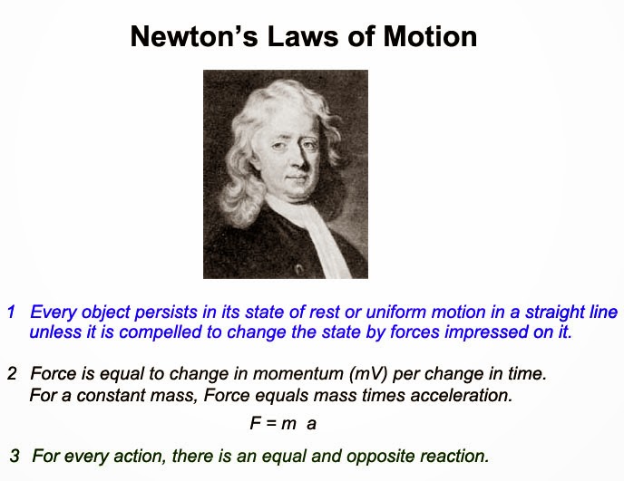
    Newton's three laws of motion

    Newton’s First Law of Motion :

    Newton’s first law of motion states that every object will remain at rest or in uniform  motion in a straight line unless compelled to its state by the action of an external force.
    The first law of motion is normally taken as the definition of inertia. If there is no net force acting on an object then object will remain a constant velocity. If an external force is applied, the velocity of body will change because of force.

    Newton’s Second law of Motion :

    Newton’s Second law of motion states that if the resultant force acting on a particle is not zero, the particle will have acceleration proportional to the magnitude of the resultant and in the direction of this resultant force.  This law explains how velocity of an object changes when it is subjected to an external force. The law defines force to be equal to change in momentum (mass times velocity) per unit time.
    For an object  with constant mass m, Newton’s second law of motion states that the force 'F' is the product of an object’s mass 'm' and its acceleration 'a'.
    F = m.a
    For an externally applied force, the acceleration depends on mass of the object and a change in velocity will generate a force. The above equation works in both ways.

    Newton’s Third Law of Motion :

    Newton’s third law of motion states that for every action (force) in nature there is an equal and opposite reaction. In other words, if object 'A' exerts a force on object 'B', then object 'B' also exerts an equal force on object 'A'.
    The third law of motion can be used to explain the generation of lift by a wing and the production of thrust by a jet engine.

    Sunday, June 15, 2014

    Heat Exchangers classification

    Heat exchanger is a process equipment designed for the effective transfer of heat energy between two fluids. For the heat transfer to occur two fluids must be at different temperatures and they must come thermal contact. Heat exchange involve convection in each fluid and conduction through the separating wall. Heat can flow only from hotter to cooler fluids, as per the second law of thermodynamics.

    Fin type heat exchanger

    Heat exchangers can be classified into four types, according to

    1. Nature of heat exchange process:

    • Direct contact heat exchanger: this is done by complete physical mixing of heat and mass transfer. Examples are water cooling towers and jet condensers in steam power plants.
    • Regenerator: here hot and cold fluids flows alternately when hot fluid passes, the heat is transferred to the solid matrix and then stopped the flow of hot fluid, next cold fluid is passed on the matrix which takes heat from solid matrix. Examples are Open hearth and blast furnaces.
    • Recuperator: the cold fluid flows simultaneously on either side of a separating wall. Examples are super heaters, condensers, economizers and air pre-heaters in steam power plants, automobile radiators.

    2. Relative direction of motion of fluids:

    According to flow of fluids, the Heat Exchangers are classified into three categories:

    2.1 Parallel flow heat exchangers:

    In parallel flow heat exchangers, both the tube side fluid and the shell side fluid flow in same direction. In this case, the two fluids enter the heat exchanger from the same end with a large temperature difference.

    2.2 Counter flow heat exchangers:

    In counter flow heat exchangers, the two fluids flow in opposite directions. Each of the fluids enter the heat exchanger from opposite ends. Because the cooler fluid exists the counter flow heat exchanger at the end where the hot fluid enters the heat exchanger, the cooler fluid will approach the inlet temperature of the hot fluid.

    2.3 Cross flow heat exchangers:

    In cross flow heat exchangers, one fluid flows through tubes and second fluid passes around the tubes perpendicularly.

    3. Mechanical Design of Heat Exchanger Surface:

    1. Concentric tubes
    2. Shell and tube
    3. Multiple shell and tube passes

    4. Physical state of heat exchanging:

    1. Condenser
    2. Evaporator

    Monday, June 9, 2014

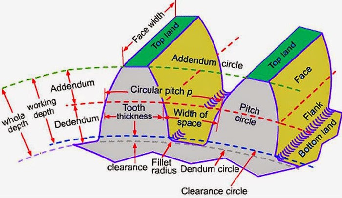
    Gear Terminology

    The following are the important dimensions and geometries concerned with toothed gear:

    Pitch Circle :

    Pitch circle is the apparent circle that two gears can be taken like smooth cylinders rolling without friction.

    Addendum Circle :

    Addendum circle is the outer most profile circle of a gear. Addendum is the radial distance between the pitch circle and the addendum circle.

    Dedendum Circle :

    Dedendum circle is the inner most profile circle. Dedendum is the radial distance between the pitch circle and the dedendum circle.

    Clearance :

    Clearance is the radial distance from top of the tooth to the bottom of the tooth space in the mating gear.

    Gear Terminology

    Backlash :

    Backlash is the tangential space between teeth of mating gears at pitch circles.

    Full Depth :

    Full depth is sum of the addendum and the dedendum.

    Face Width :

    Face width is length of tooth parallel to axes.

    Diametral Pitch :

    Diametral pitch (p) is the number of teeth per unit volume.
    p =  (Number of Teeth) / (Diameter of Pitch circle)

    Module :

    Module (m) is the inverse of diametral pitch.

    m = 1/p

    Circular Pitch :

    Circular pitch is the space in pitch circle used by each teeth.

    Gear Ratio :

    Gear ratio is numbers of teeth of larger gear to smaller gear.

    Pressure Line :

    Pressure line is the common normal at the point of contact of mating gears along which the driving tooth exerts force on the driven tooth.

    Pressure Angle :

    Pressure angle is the angle between the pressure line and common tangent to pitch circles. It is also called angle of obliquity. high pressure angle requires wider base and stronger teeth.

    Pitch Angle :

    Pitch angle is the angle captured by a tooth.
    Pitch angle = 360/T

    Contact Ratio :

    Contact ratio is angle of angle of action and pitch angle.

    Path of Approach :

    Path of approach is the distance along the pressure line traveled by the contact point from the point of engagement to the pitch point.

    Path of Recess :

    Path of recess is the distance traveled along the pressure line by the contact point from the pitch point to the path of disengagement.

    Path of Contact :

    Patch of contact is the sum of path of approach and path of recess.

    Arc of Approach :

    Arc of approach is the distance traveled by a point on either pitch circle of the two wheels from the point of engagement to the pitch.

    Arc of Recess :

    Arc of recess is the distance traveled by a point on either pitch circle of the two wheels from the point to the point of disengagement.

    Arc of Contact :

    Arc of contact is the distance traveled by a point on either pitch circle of the two wheels during the period of contact of a pair of teeth.

    Angle of Action :

    Angle of action is the angle turned by a gear during arc of contact.


    Sunday, June 1, 2014

    Classification of Gears

    Gears can be classified according to relative positions of their shaft axes into three types. They are:
    1. Gears for Parallel shafts
    2. Gears for Intersecting Shafts
    3. Gears for Skew Shafts

    Types of gears

    1. Gears for Parallel Shafts:

    The motion between parallel shafts is same as to the rolling of two cylinders. Gears under this category are the following:

    1.1 Spur Gears:

    Straight Spur gears are the simplest form of gears having teeth parallel to the gear axis. The contact of two teeth takes place over the entire width along a line parallel to the axes of rotation. As gear rotate , the line of contact goes on shifting parallel to the shaft.

    Spur Gears


    1.2 Helical Gears:

    In helical gear teeth are part of helix instead of straight across the gear parallel to the axis. The mating gears will have same helix angle but in opposite direction for proper mating. As the gear rotates, the contact shifts along the line of contact in in volute helicoid across the teeth.


    Helical Gears

    1.3 Herringbone Gears:

    Herringbone gears are also known as Double Helical Gears. Herringbone gears are made of two helical gears with opposite helix angles, which can be up to 45 degrees.


    Herringbone gears

    1.4 Rack and Pinion:

    In these gears the spur rack can be considered to be spur gear of infinite pitch radius with its axis of rotation placed at infinity parallel to that of pinion. The pinion rotates while the rack translates.


    Rack and Pininon


    2. Gears for Intersecting Shafts:

    The motion between two intersecting shafts is equivalent to the rolling of two cones. The gears used for intersecting shafts are called bevel gears. Gears under this category are following: 

    2.1 Straight Bevel Gears:

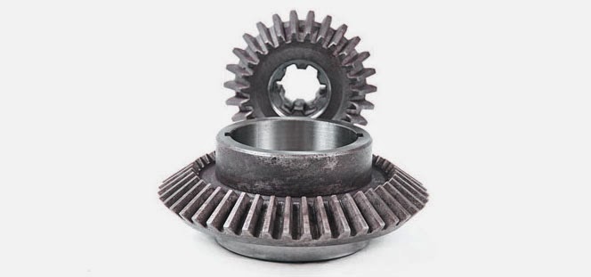
    Straight bevel gears are provided with straight teeth, radial to the point of intersection of the shaft axes and vary in cross section through the length inside generator of the cone. Straight Bevel Gears can be seen as modified version of straight spur gears in which teeth are made in conical direction instead of parallel to axis.

    Straight Bevel Gears

    2.2 Spiral Bevel Gears:

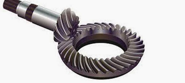
    Bevel gears are made with their teeth are inclined at an angle to face of the bevel. Spiral gears are also known as helical bevels.


    Spiral Bevel Gears


    3. Gears for Skew Shafts:

    The following gears are used to join two non-parallel and non-intersecting shafts.

    3.1 Hypoid Gears:

    The Hypoid Gears are made of the frusta of hyperboloids of revolution. Two matching hypoid gears are made by revolving the same line of contact, these gears are not interchangeable.

    Hypoid Gears

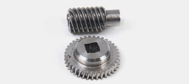
    3.2 Worm Gears:

    The Worm Gears are used to connect skewed shafts, but not necessarily at right angles. Teeth on worm gear are cut continuously like the threads on a screw. The gear meshing with the worm gear is known as worm wheel and combination is known as worm and worm wheel.

    Worm Gears

    Friday, May 30, 2014

    Classification of Automobiles

    An automobile is a vehicle that is capable of propelling itself. Since 17th century, several attempts have been made to design and construct a practically operative automobile.
    Today, automobiles play crucial role in the social, economic and industrial growth of any country.
    After the designing of Internal Combustion Engines, the Automobile industries has seen a tremendous growth.


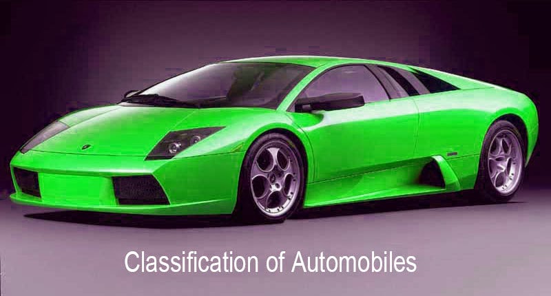
    Automobile - Lamborghini car

    Classification of Automobiles :

    Automobiles can be classified into several types based on many criteria. A brief classification of automobiles is listed below:

    1. Based on Purpose :

    • Passenger vehicles : These vehicles carry passengers. e.g: Buses, Cars, passenger trains.
    • Goods vehicles : These vehicles carry goods from one place to another place. e.g: Goods lorry, Goods carrier.
    • Special Purpose : These vehicles include Ambulance, Fire engines, Army Vehicles.

    2. Based on Load Capacity:

    • Light duty vehicle : Small motor vehicles. eg: Car, jeep, Scooter, motor cycle
    • Heavy duty vehicle :  large and bulky motor vehicles. e.g: Bus, Truck, Tractor

    3. Based on fuel used:

    • Petrol engine vehicles : Automobiles powered by petrol engine. e.g: scooters, cars, motorcycles.
    • Diesel engine vehicles : Automobiles powered by diesel engine. e.g: Trucks, Buses, Tractors.
    • Gas vehicles : Vehicles that use gas turbine as power source. e.g: Turbine powered cars.
    • Electric vehicles : Automobiles that use electricity as a power source. e.g: Electric cars, electric buses.
    • Steam Engine vehicles : Automobiles powered by steam engine. e.g: Steamboat, steam locomotive, steam wagon.

    4. Based on Drive of the vehicles :

    • Left Hand drive : Steering wheel fitted on left hand side
    • Right Hand drive : Steering wheel fitted on right hand side
    • Fluid drive : Vehicles employing torque converter, fluid fly wheel or hydramatic transmission.

    5. Based on number of wheels and axles :

    • Two wheeler : motor cycles, scooters
    • Three wheeler : Tempo, auto-rickshaws
    • Four wheeler : car, Jeep, Bus, truck
    • Six wheeler : Buses and trucks have six tires out of which four are carried on the rear wheels for additional reaction.
    • Six axle wheeler : Dodge(10 tire) vehicle

    6. Based on type of transmission:

    • Automatic transmission vehicles: Automobiles that are capable of changing gear ratios automatically as they move. e.g: Automatic Transmission Cars.
    • Manual transmission vehicles: Automobiles whose gear ratios have to be changed manually.
    • Semi-automatic transmission vehicles: Vehicles that facilitate manual gear changing with clutch pedal.

    7. Based on Suspension system used:

    • Convectional - Leaf Spring
    • Independent - Coil spring, Torsion bar, Pneumatic.

    Wednesday, May 21, 2014

    Modes of Heat Transfer - Conduction, Convection and Radiation

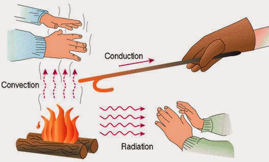
    Heat is a form of energy which transfers between bodies which are kept under thermal interactions. When a temperature difference occurs between two bodies or a body with its surroundings, heat transfer occurs.
    Heat transfer occurs in three modes:
    1) Conduction 2) Convection and 3) Radiation

    modes of heat transfer


    Conduction :

    In Conduction, heat transfer takes place due to temperature difference in a body or between bodies in thermal contact, without mixing of mass. The rate of heat transfer through conduction is governed by the Fourier's law of heat conduction.
    Q = -kA(dT/dx)
    Where: Q is the heat flow rate by conduction
    K is the thermal conductivity of body material
    A is the cross-sectional area normal to direction of heat flow and
    dT/dx is the temperature gradient of the section.


    Convection :

    In convection, heat is transferred to a moving fluid at the surface over which it flows by combined molecular diffusion and bulk flow. Convection involves conduction and fluid flow. The rate of convective heat transfer is governed by the Newton's law of cooling.
    Q = hA(Ts-T∞)
    Where: Ts is the surface temperature
    T∞ is the outside temperature
    h is the coefficient of convection
    heat transfer occurs in three modes, they are conduction, convection and radiation

    Radiation:

    In radiation, heat is transferred in the form of radiant energy or wave motion from one body to another body. No medium for radiation to occur. The rate of heat radiation that can be emitted by a surface at a thermodynamic temperature is based on Stefan-Boltzmann law.
    Q = σT⁴
    Where: T is the absolute temperature of surface
    σ is the Stefan-Boltzmann constant.