Showing posts with label Theory of Machines. Show all posts

Friday, July 4, 2014

Governor types - Centrifugal Governor and Inertia Governor

Governor is a device used to maintain the speed of an engine within specified limits when the engine works in varying of different loads.
Based on the source of controlling force, the governors can be classified into two types. They are centrifugal governors and inertia governors.

Centrifugal Governors :

In centrifugal governors, multiple masses know as governor balls, are responsible to revolve about the axis of a shaft, which is driven through suitable gearing from the engine crankshaft. Each ball is acted upon by a force which acts in the radially inward direction and is provided by dead weight, a spring or a combination of two. This force is commonly called as the controlling force and it will increase as the distance of the ball from the axis of rotation increases. The inward or outward movement of the ball is transmitted by the governor mechanism to the valve which controls the amount of energy supplied to the engine.

Centrifugal governor
Image Source : flickr.com

Inertia Governor :

In inertia governors, the balls are arranged in manner that the inertia forces caused by angular acceleration or retardation of the governor shaft tend to change their position. The obvious advantage of inertia governor lies in its rapid response to the effect of a change of load. This advantage is small, however by the practical difficulty of arranging for the complete balance of the revolving parts of the governor. For this reason Centrifugal governors are preferred over the inertia governors.




Wednesday, June 25, 2014

Belt Drives

A belt is a looped strip of flexible material used to mechanically link two or more rotating shafts. A belt drive offers smooth transmission of power between shafts at considerable distance. Belt drives are used as source of motion to transfer to efficiently transmit power or to track relative movement.

Image source : wwag.com

Types of Belt Drives:

In a two pulley system, depending upon direction the belt drives the pulley, the belt drives are divided into two types. They are open belt drive and crossed belt drive. The two types of belt drives are discussed below in brief.

Open belt drives :

open belt drive
An open belt drive is used to rotate the driven pulley in the same direction of driving pulley.  In motion of belt drive, power transmission results makes one side of pulley more tightened compared to the other side.  In horizontal drives, tightened side is always kept in the lower side of two pulleys because the sag of the upper side slightly increases the angle of folding of the belt on the two pulleys.

Crossed belt drive
Crossed belt drives :

A crossed belt drive is used to rotate driven pulley in the opposite direction of driving pulley. Higher the value of wrap enables more power can be transmitted than an open belt drive. However, bending and wear of the belt are important concerns.

Advantages of belt drives :

  • Belt drives are simple are economical.
  • They don't require Parallel shafts.
  • Belts drives are provided with overload and jam protection.
  • Noise and vibration are damped out. Machinery life is increased because load fluctuations are shock-absorbed.
  • They are lubrication-free. They require less maintenance cost.
  • Belt drives are highly efficient in use (up to 98%, usually 95%).
  • They are very economical, when distance between shafts is very large.

Disadvantages of belt drives :

  • In Belt drives, angular velocity ratio is not necessarily constant or equal to the ratio of pulley diameters, because of slipping and stretching.
  • Heat buildup occurs. Speed is limited to usually 35 meters per second. Power transmission is limited to 370 kilowatts.
  • Operating temperatures are usually restricted to –35 to 85°C.
  • Some adjustment of center distance or use of an idler pulley is necessary for wearing and stretching of belt drive compensation. 


    Monday, June 9, 2014

    Gear Terminology

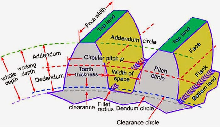
    The following are the important dimensions and geometries concerned with toothed gear:

    Pitch Circle :

    Pitch circle is the apparent circle that two gears can be taken like smooth cylinders rolling without friction.

    Addendum Circle :

    Addendum circle is the outer most profile circle of a gear. Addendum is the radial distance between the pitch circle and the addendum circle.

    Dedendum Circle :

    Dedendum circle is the inner most profile circle. Dedendum is the radial distance between the pitch circle and the dedendum circle.

    Clearance :

    Clearance is the radial distance from top of the tooth to the bottom of the tooth space in the mating gear.

    Gear Terminology

    Backlash :

    Backlash is the tangential space between teeth of mating gears at pitch circles.

    Full Depth :

    Full depth is sum of the addendum and the dedendum.

    Face Width :

    Face width is length of tooth parallel to axes.

    Diametral Pitch :

    Diametral pitch (p) is the number of teeth per unit volume.
    p =  (Number of Teeth) / (Diameter of Pitch circle)

    Module :

    Module (m) is the inverse of diametral pitch.

    m = 1/p

    Circular Pitch :

    Circular pitch is the space in pitch circle used by each teeth.

    Gear Ratio :

    Gear ratio is numbers of teeth of larger gear to smaller gear.

    Pressure Line :

    Pressure line is the common normal at the point of contact of mating gears along which the driving tooth exerts force on the driven tooth.

    Pressure Angle :

    Pressure angle is the angle between the pressure line and common tangent to pitch circles. It is also called angle of obliquity. high pressure angle requires wider base and stronger teeth.

    Pitch Angle :

    Pitch angle is the angle captured by a tooth.
    Pitch angle = 360/T

    Contact Ratio :

    Contact ratio is angle of angle of action and pitch angle.

    Path of Approach :

    Path of approach is the distance along the pressure line traveled by the contact point from the point of engagement to the pitch point.

    Path of Recess :

    Path of recess is the distance traveled along the pressure line by the contact point from the pitch point to the path of disengagement.

    Path of Contact :

    Patch of contact is the sum of path of approach and path of recess.

    Arc of Approach :

    Arc of approach is the distance traveled by a point on either pitch circle of the two wheels from the point of engagement to the pitch.

    Arc of Recess :

    Arc of recess is the distance traveled by a point on either pitch circle of the two wheels from the point to the point of disengagement.

    Arc of Contact :

    Arc of contact is the distance traveled by a point on either pitch circle of the two wheels during the period of contact of a pair of teeth.

    Angle of Action :

    Angle of action is the angle turned by a gear during arc of contact.


    Sunday, June 1, 2014

    Classification of Gears

    Gears can be classified according to relative positions of their shaft axes into three types. They are:
    1. Gears for Parallel shafts
    2. Gears for Intersecting Shafts
    3. Gears for Skew Shafts

    Types of gears

    1. Gears for Parallel Shafts:

    The motion between parallel shafts is same as to the rolling of two cylinders. Gears under this category are the following:

    1.1 Spur Gears:

    Straight Spur gears are the simplest form of gears having teeth parallel to the gear axis. The contact of two teeth takes place over the entire width along a line parallel to the axes of rotation. As gear rotate , the line of contact goes on shifting parallel to the shaft.

    Spur Gears


    1.2 Helical Gears:

    In helical gear teeth are part of helix instead of straight across the gear parallel to the axis. The mating gears will have same helix angle but in opposite direction for proper mating. As the gear rotates, the contact shifts along the line of contact in in volute helicoid across the teeth.


    Helical Gears

    1.3 Herringbone Gears:

    Herringbone gears are also known as Double Helical Gears. Herringbone gears are made of two helical gears with opposite helix angles, which can be up to 45 degrees.


    Herringbone gears

    1.4 Rack and Pinion:

    In these gears the spur rack can be considered to be spur gear of infinite pitch radius with its axis of rotation placed at infinity parallel to that of pinion. The pinion rotates while the rack translates.


    Rack and Pininon


    2. Gears for Intersecting Shafts:

    The motion between two intersecting shafts is equivalent to the rolling of two cones. The gears used for intersecting shafts are called bevel gears. Gears under this category are following: 

    2.1 Straight Bevel Gears:

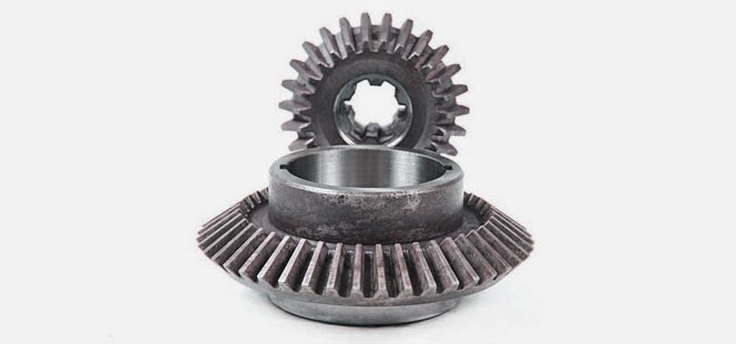
    Straight bevel gears are provided with straight teeth, radial to the point of intersection of the shaft axes and vary in cross section through the length inside generator of the cone. Straight Bevel Gears can be seen as modified version of straight spur gears in which teeth are made in conical direction instead of parallel to axis.

    Straight Bevel Gears

    2.2 Spiral Bevel Gears:

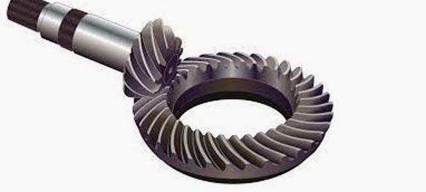
    Bevel gears are made with their teeth are inclined at an angle to face of the bevel. Spiral gears are also known as helical bevels.


    Spiral Bevel Gears


    3. Gears for Skew Shafts:

    The following gears are used to join two non-parallel and non-intersecting shafts.

    3.1 Hypoid Gears:

    The Hypoid Gears are made of the frusta of hyperboloids of revolution. Two matching hypoid gears are made by revolving the same line of contact, these gears are not interchangeable.

    Hypoid Gears

    3.2 Worm Gears:

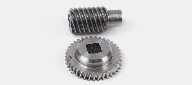
    The Worm Gears are used to connect skewed shafts, but not necessarily at right angles. Teeth on worm gear are cut continuously like the threads on a screw. The gear meshing with the worm gear is known as worm wheel and combination is known as worm and worm wheel.

    Worm Gears