Sunday, June 1, 2014

Classification of Gears

Gears can be classified according to relative positions of their shaft axes into three types. They are:
1. Gears for Parallel shafts
2. Gears for Intersecting Shafts
3. Gears for Skew Shafts

Types of gears

1. Gears for Parallel Shafts:

The motion between parallel shafts is same as to the rolling of two cylinders. Gears under this category are the following:

1.1 Spur Gears:

Straight Spur gears are the simplest form of gears having teeth parallel to the gear axis. The contact of two teeth takes place over the entire width along a line parallel to the axes of rotation. As gear rotate , the line of contact goes on shifting parallel to the shaft.

Spur Gears


1.2 Helical Gears:

In helical gear teeth are part of helix instead of straight across the gear parallel to the axis. The mating gears will have same helix angle but in opposite direction for proper mating. As the gear rotates, the contact shifts along the line of contact in in volute helicoid across the teeth.


Helical Gears

1.3 Herringbone Gears:

Herringbone gears are also known as Double Helical Gears. Herringbone gears are made of two helical gears with opposite helix angles, which can be up to 45 degrees.


Herringbone gears

1.4 Rack and Pinion:

In these gears the spur rack can be considered to be spur gear of infinite pitch radius with its axis of rotation placed at infinity parallel to that of pinion. The pinion rotates while the rack translates.


Rack and Pininon


2. Gears for Intersecting Shafts:

The motion between two intersecting shafts is equivalent to the rolling of two cones. The gears used for intersecting shafts are called bevel gears. Gears under this category are following: 

2.1 Straight Bevel Gears:

Straight bevel gears are provided with straight teeth, radial to the point of intersection of the shaft axes and vary in cross section through the length inside generator of the cone. Straight Bevel Gears can be seen as modified version of straight spur gears in which teeth are made in conical direction instead of parallel to axis.
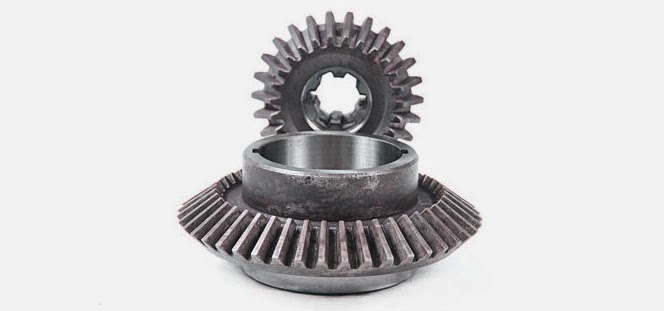
Straight Bevel Gears

2.2 Spiral Bevel Gears:

Bevel gears are made with their teeth are inclined at an angle to face of the bevel. Spiral gears are also known as helical bevels.
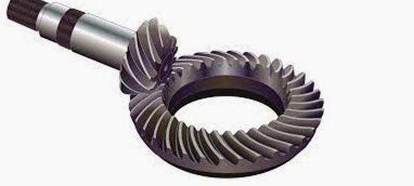

Spiral Bevel Gears


3. Gears for Skew Shafts:

The following gears are used to join two non-parallel and non-intersecting shafts.

3.1 Hypoid Gears:

The Hypoid Gears are made of the frusta of hyperboloids of revolution. Two matching hypoid gears are made by revolving the same line of contact, these gears are not interchangeable.

Hypoid Gears

3.2 Worm Gears:

The Worm Gears are used to connect skewed shafts, but not necessarily at right angles. Teeth on worm gear are cut continuously like the threads on a screw. The gear meshing with the worm gear is known as worm wheel and combination is known as worm and worm wheel.
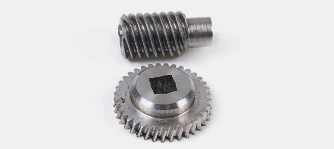
Worm Gears

Friday, May 30, 2014

Classification of Automobiles

An automobile is a vehicle that is capable of propelling itself. Since 17th century, several attempts have been made to design and construct a practically operative automobile.
Today, automobiles play crucial role in the social, economic and industrial growth of any country.
After the designing of Internal Combustion Engines, the Automobile industries has seen a tremendous growth.


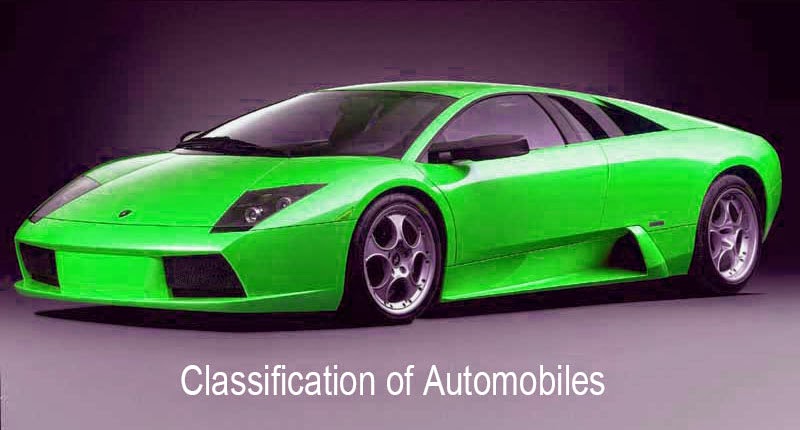
Automobile - Lamborghini car

Classification of Automobiles :

Automobiles can be classified into several types based on many criteria. A brief classification of automobiles is listed below:

1. Based on Purpose :

  • Passenger vehicles : These vehicles carry passengers. e.g: Buses, Cars, passenger trains.
  • Goods vehicles : These vehicles carry goods from one place to another place. e.g: Goods lorry, Goods carrier.
  • Special Purpose : These vehicles include Ambulance, Fire engines, Army Vehicles.

2. Based on Load Capacity:

  • Light duty vehicle : Small motor vehicles. eg: Car, jeep, Scooter, motor cycle
  • Heavy duty vehicle :  large and bulky motor vehicles. e.g: Bus, Truck, Tractor

3. Based on fuel used:

  • Petrol engine vehicles : Automobiles powered by petrol engine. e.g: scooters, cars, motorcycles.
  • Diesel engine vehicles : Automobiles powered by diesel engine. e.g: Trucks, Buses, Tractors.
  • Gas vehicles : Vehicles that use gas turbine as power source. e.g: Turbine powered cars.
  • Electric vehicles : Automobiles that use electricity as a power source. e.g: Electric cars, electric buses.
  • Steam Engine vehicles : Automobiles powered by steam engine. e.g: Steamboat, steam locomotive, steam wagon.

4. Based on Drive of the vehicles :

  • Left Hand drive : Steering wheel fitted on left hand side
  • Right Hand drive : Steering wheel fitted on right hand side
  • Fluid drive : Vehicles employing torque converter, fluid fly wheel or hydramatic transmission.

5. Based on number of wheels and axles :

  • Two wheeler : motor cycles, scooters
  • Three wheeler : Tempo, auto-rickshaws
  • Four wheeler : car, Jeep, Bus, truck
  • Six wheeler : Buses and trucks have six tires out of which four are carried on the rear wheels for additional reaction.
  • Six axle wheeler : Dodge(10 tire) vehicle

6. Based on type of transmission:

  • Automatic transmission vehicles: Automobiles that are capable of changing gear ratios automatically as they move. e.g: Automatic Transmission Cars.
  • Manual transmission vehicles: Automobiles whose gear ratios have to be changed manually.
  • Semi-automatic transmission vehicles: Vehicles that facilitate manual gear changing with clutch pedal.

7. Based on Suspension system used:

  • Convectional - Leaf Spring
  • Independent - Coil spring, Torsion bar, Pneumatic.

Wednesday, May 21, 2014

Modes of Heat Transfer - Conduction, Convection and Radiation

Heat is a form of energy which transfers between bodies which are kept under thermal interactions. When a temperature difference occurs between two bodies or a body with its surroundings, heat transfer occurs.
Heat transfer occurs in three modes:
1) Conduction 2) Convection and 3) Radiation

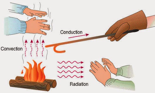
modes of heat transfer


Conduction :

In Conduction, heat transfer takes place due to temperature difference in a body or between bodies in thermal contact, without mixing of mass. The rate of heat transfer through conduction is governed by the Fourier's law of heat conduction.
Q = -kA(dT/dx)
Where: Q is the heat flow rate by conduction
K is the thermal conductivity of body material
A is the cross-sectional area normal to direction of heat flow and
dT/dx is the temperature gradient of the section.


Convection :

In convection, heat is transferred to a moving fluid at the surface over which it flows by combined molecular diffusion and bulk flow. Convection involves conduction and fluid flow. The rate of convective heat transfer is governed by the Newton's law of cooling.
Q = hA(Ts-T∞)
Where: Ts is the surface temperature
T∞ is the outside temperature
h is the coefficient of convection
heat transfer occurs in three modes, they are conduction, convection and radiation

Radiation:

In radiation, heat is transferred in the form of radiant energy or wave motion from one body to another body. No medium for radiation to occur. The rate of heat radiation that can be emitted by a surface at a thermodynamic temperature is based on Stefan-Boltzmann law.
Q = σT⁴
Where: T is the absolute temperature of surface
σ is the Stefan-Boltzmann constant.

Friday, April 18, 2014

Brake System Classification

Brake system used to slow down a vehicle by converting its kinetic energy into heat energy.

Disk brake of a bike

Classification of Brake system :

On the basis of mode of actuation

  • Foot brake (also called main brake) operated by foot pedal
  • Hand brake – it is also called parking brake operated by hand

On the basis of mode of operation

  • Air brakes
  • Electric brakes
  • Hydraulic brakes
  • Mechanical brakes
  • Vacuum brakes

On the Basis of Action on Front or Rear Wheels

  • Front-wheel brakes
  • Rear-wheel brakes

On the Basis of Method of Application of Braking Contact

  • Externally – contracting brakes
  • Internally – expanding brakes

Thursday, April 17, 2014

Types of fluid flow in pipes - laminar, turbulent, transient

Pipes are in circular cross section area, identical to the shape of a roll of paper towels. We general use pipes in our homes to supply water from water tank to kitchen, bathroom.

Fluid flow can be classified into three types:

  • Laminar flow
  • Turbulent flow
  • Transitional flow

Laminar flow :

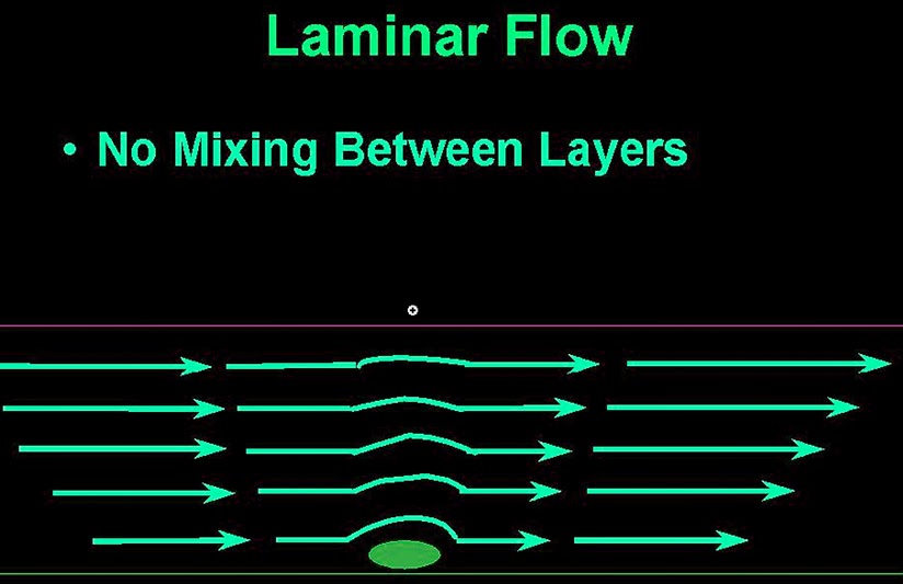
Occurs when the fluid flows in parallel layers, with no mixing between the layers. Where the center part of the pipe flow the fastest and the cylinder touching the pipe isn't moving at all.
The flow is laminar when Reynolds number is less than 2300.

Laminar flow in pipes

Turbulent flow :

In turbulent flow occurs when the liquid is moving fast with mixing between layers. The speed of the fluid at a point is continuously undergoing changes in both magnitude and direction.
The flow is turbulent when Reynolds number greater than 4000.

Turbulent flow in pipes

Transitional flow :

Transitional flow is a mixture of laminar and turbulent flow, with turbulence flow in the center of the pipe and laminar flow near the edges of the pipe. Each of these flows behave in different manners in terms of their frictional energy loss while flowing and have different equations that predict their behavior.
The flow is transitional when Reynolds number is in between 2300 and 4000.

Wednesday, April 2, 2014

Centrifugal pump efficiency - Mechanical, Hydraulic, Volumetric, Overall efficiencies

Performance of a centrifugal pump can be determined by finding the following efficiencies:
  • Mechanical efficiency
  • Hydraulic efficiency
  • Volumetric efficiency
  • Overall efficiency
Centrifugal pump efficiencies

Mechanical efficiency of a centrifugal pump (ηm):

Mechanical efficiency of a centrifugal pump (ηm) is the ratio of theoretical power that must be supplied to operate the pump to the actual power delivered to the pump.
Mechanical efficiency can be used to determine the power loss in bearings and other moving parts of a centrifugal pump. It determines the actual power that must be supplied to a centrifugal pump for desired result.
Mechanical efficiency of a centrifugal pump

Hydraulic efficiency of a centrifugal pump (ηH):

Hydraulic efficiency of a centrifugal pump (ηH) is defined as the ratio of the useful hydrodynamic energy in fluid to Mechanical energy supplied to rotor.
Hydraulic efficiency of a centrifugal pump

Volumetric efficiency of a centrifugal pump (ηv):

Volumetric efficiency of a centrifugal pump (ηv) is defined as the ratio of the actual flow rate delivered by the pump to the theoretical discharge flow rate (flow rate without any leakage) that must be produced by the pump.
Volumetric efficiency can be used to determine the amount of loss of liquid due to leakage in a pump during the flow.

Volumetric efficiency of a centrifugal pump


Overall efficiency of a centrifugal pump (ηo):

Overall efficiency of a centrifugal pump is the ratio of the actual power output of a pump to the actual power input to the pump. It is the efficiency that determines the overall energy loss in a centrifugal pump.
Overall efficiency of a centrifugal pump

Overall efficiency of a centrifugal pump is the product of the volumetric efficiency and mechanical efficiency of a centrifugal pump.
Overall efficiency of a centrifugal pump (ηo) = Mechanical efficiency (ηm) × Volumetric efficiency (ηv)

Saturday, March 15, 2014

Types of Fluids

fluids are divided into two types they are Newtonian fluids and Non-Newtonian fluids.
Fluids are defined as substance that flow or deform under the applied shear stress. Fluid has no definite shape of its own. It assumes the shape of its container. Liquids and gases are known as fluids.

Types of Fluids:

Depending on the behavior of fluids, fluids are divided into two types. They are 

  • Newtonian Fluid
  • Non-Newtonian Fluid
Below about these types of fluids are discussed in brief.

Newtonian Fluid:

Fluids that obey Newton law of viscosity are known as Newtonian Fluids.
Newton law of viscosity states that the shear stress on a fluid element layer is directly proportional to the rate of shear strain.
Examples of Newtonian fluids : water, air, kerosene 

Non-Newtonian Fluid:

Fluids that doesn't obey Newton law of viscosity are known as Non-Newtonian fluids. These fluids are the opposite of Newtonian fluids.
Examples of Non-Newtonian fluids : colloids, thick slurry, emulsions.